March
30, 2008
Following
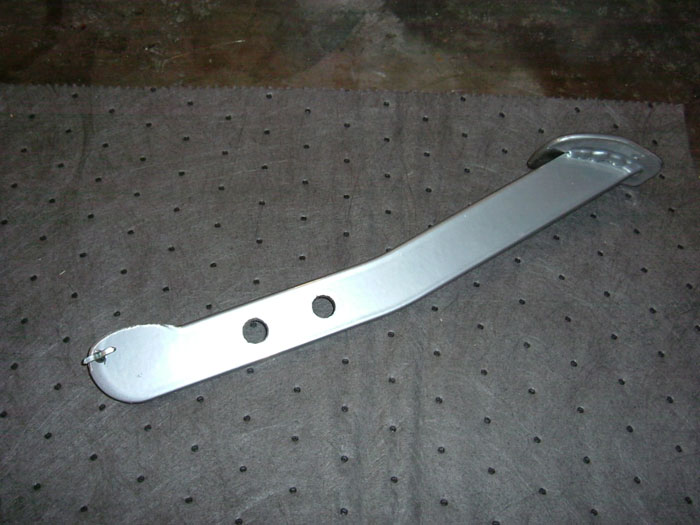
the directions for the brake pedal, I drilled a new hole in
the pedal 12.7mm below the original hole. (Center to center,
same size) Then installed the new pivot bracket. The bottom
of the pedal that contacts the master cylinder plunger will
most likely need to have some material removed so that there
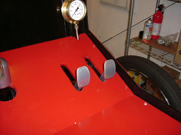
is some free play in the pedal movement. So when the floor is
in place and the pedal is in the release position; it is not
pushing on the master cylinder plunger, an 1/8th inch clearance
is fine. I had to add a large washer to take up the space between
the bracket and the pedal for better pedal stability on the
pivot clevis. Then hooked up my return spring. (See Kit 3 brakes)
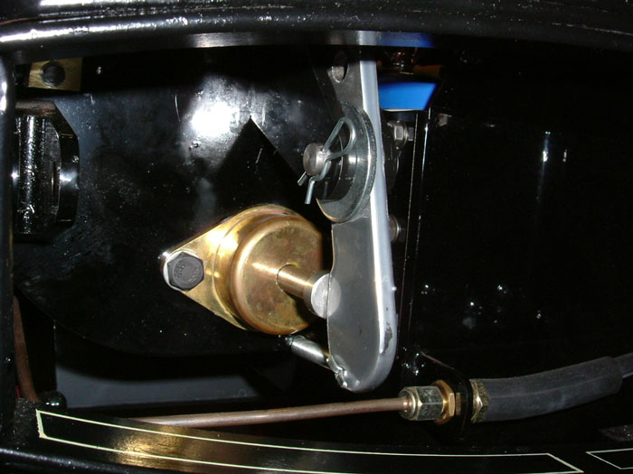
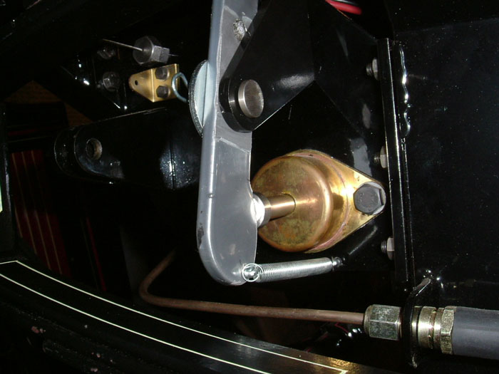
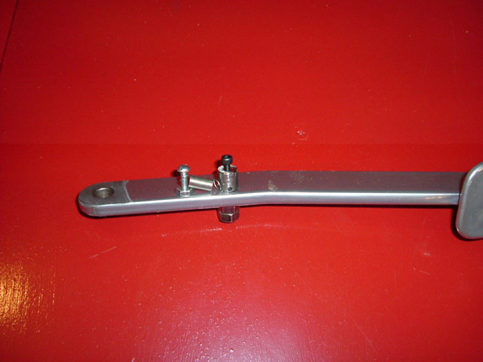
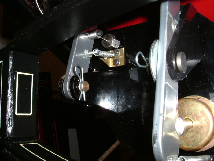
The throttle pedal is fairly straight forward; this is how I
installed mine. On the throttle pedal there is an existing hole
for a return spring; I tapped the hole to accept a 6-32 machine
screw, I also drilled out the return spring bracket to fit another
6-32 machine screw. I fit the machine screws to the bracket
and the pedal; this is where my return spring will mount. Fit
the cable connector to the pedal and double nut, making sure
the cable connector can rotate freely in the pedal. I used several
washers on the pedal clevis for pedal stability. You'll note
in the pictures I used hairpin clips on the clevis pins for
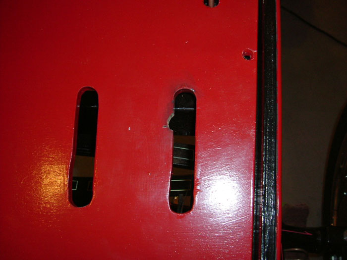
easier future servicing. I cut a small notch in the floorboard
to allow the pedal to be installed and removed easier with the
cable connector attached. Thread the cable through the connector,
adjust the pedal movement, and lock with the allen bolt, install
the return spring between the 2 machine screws.
3.0 Hours
March
31
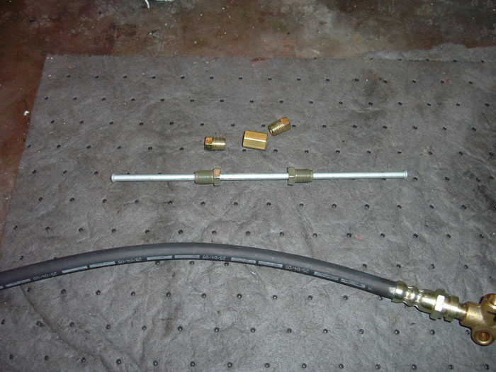
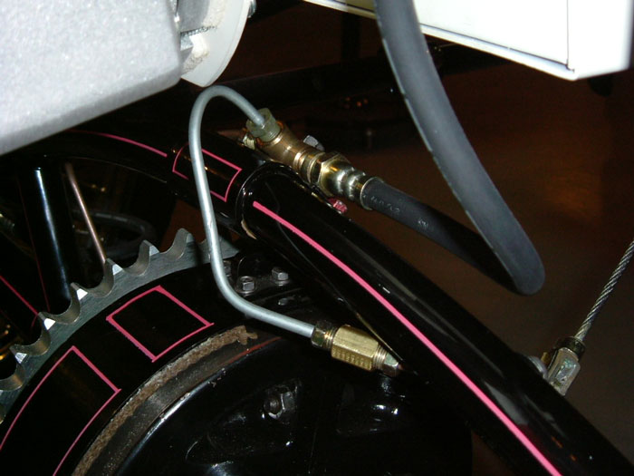
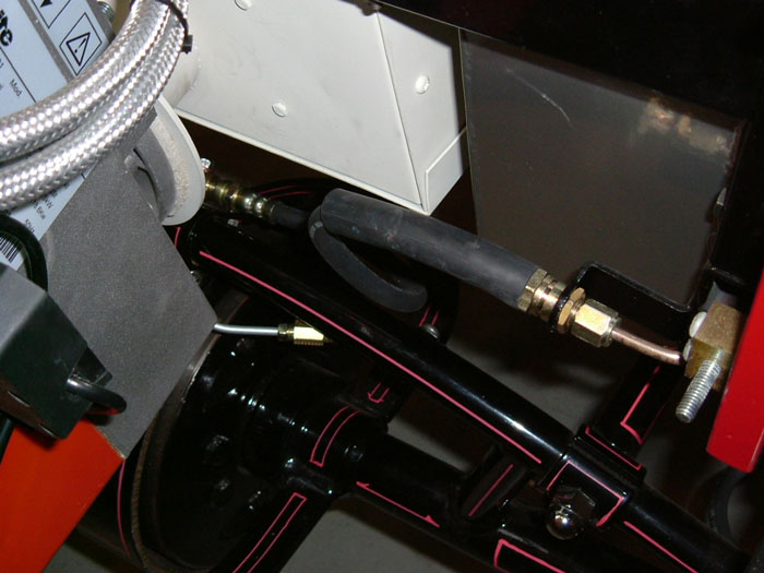
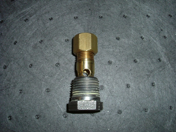
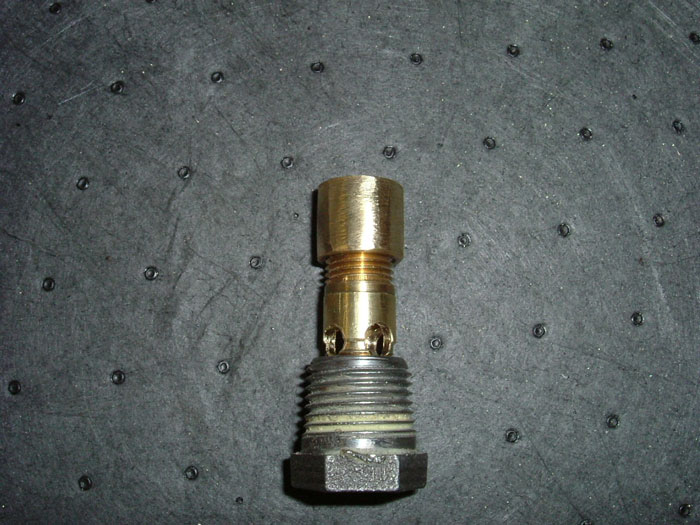
You may have noticed that the rear brake flex line comes in
contact with the burner flange; I chose to reroute my flex line
to eliminate this problem. Using a 6" long 3/16 metric
brake line with bubble flare, a pair of 3/16 tube nuts and a
union, all available at your local automotive store; I cut off
one end of the new brake line and installed a tube nut and double
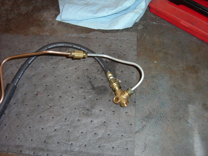
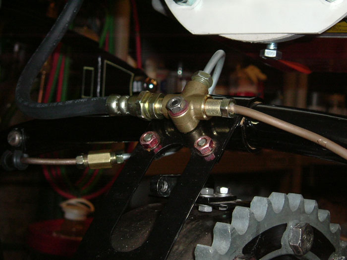
flared the end. With the bubble end of the line installed in
the top hole of the Tee fitting, using a tubing bender, bend
the line over and around the rear axle supporting tube to line
up with the r/rear brake line. Mark this location and cut the
brake line and install the other tube nut and double flare the
line, join the 2 lines together with the union. Now thread the
flex line into the side fitting of the Tee and adjust the flex
line so as to clear any possible rubbing. Now all the brake
lines are clear and away from the burner flange.
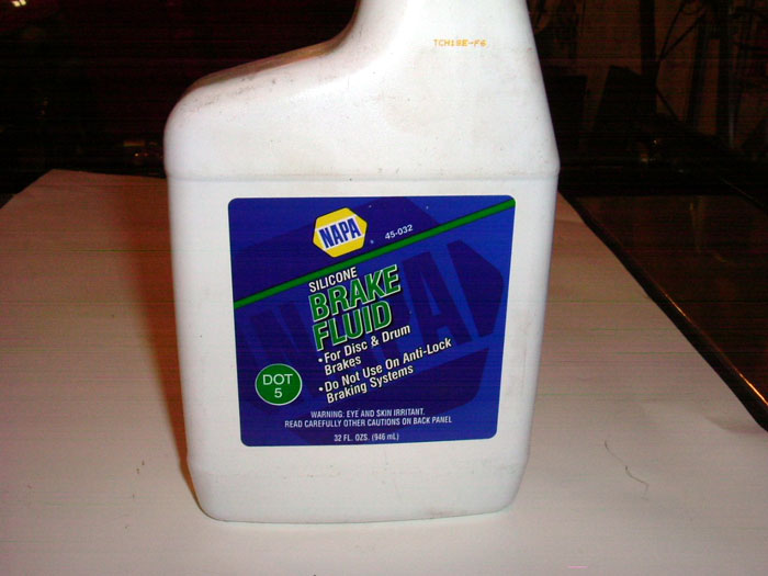
Bleeding the Brakes: Use only Dot 5 Silicone Brake Fluid,; a
power vacuum brake bleeder or a hand vacuum bleeder is a must
for bleeding Silicone fluid. The pump and press method will
only cause the fluid to foam and not completely bleed out all
the air in the system. Silicone fluid does not attract moisture
like regular brake fluid, also; it won't damage your paint should
you get any on your chassis. Recheck every fitting in the brake
system and make sure it is tight. Add the fluid to the reservoirs
and bleed the system. Note: if you have never bled brakes, or
don't understand the importance of doing it correctly; get someone
who knows to help you. This is an important safety issue, plus
you can learn how to do it for the next project.
The pedal should be high and hard without any fade or
pedal sinking with your foot on the pedal. Check for any leaks,
correct if necessary.
2.0 Hours
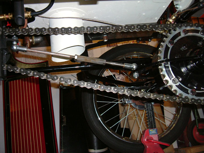
Chain Installation: To make it easier; I tied a wire onto the
first link and put the reversing lever into reverse. (This allows
more working clearance) From the rear of the engine, feed the
wire and the chain over the top of the engine sprocket and around
it, to exit bellow the tensioner rod bracket. Feed the chain
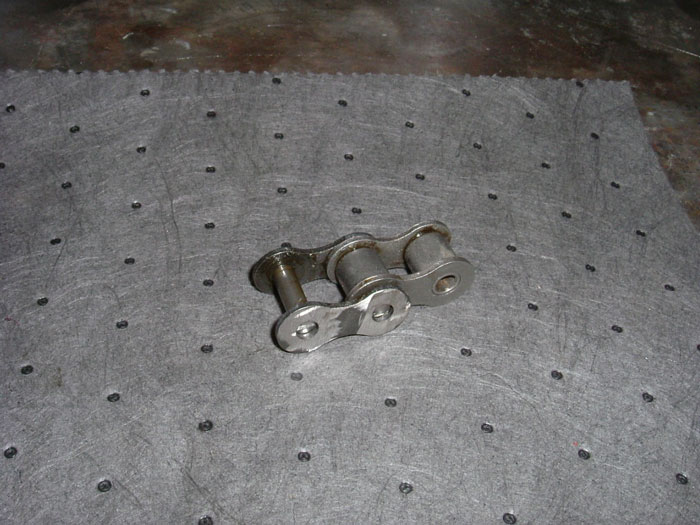
around the rear axle sprocket, join the ends with the Master
Link. My chain was too long, and had to cut off 2 sections (1
complete link). Using a cutoff wheel, I cut the 2 peened pins
flush with the connector link face and drove out the 2 pins
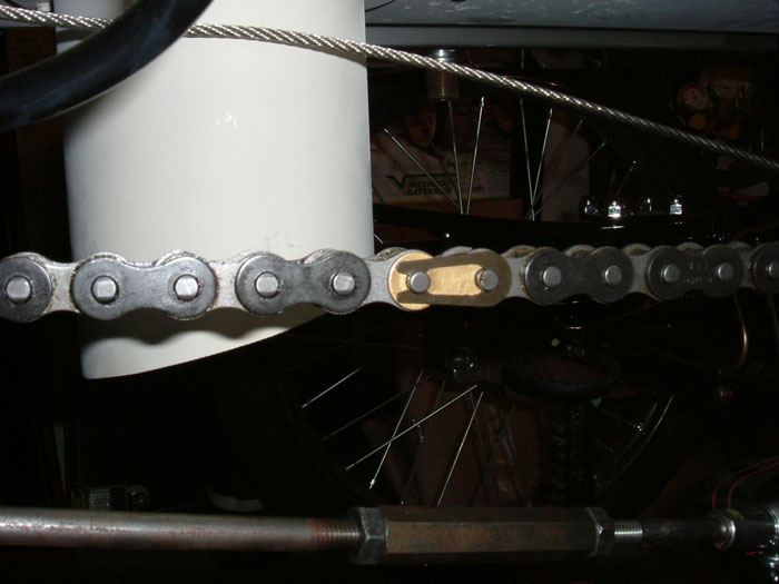
together and removed the link from the chain. Reinstall the
chain, I used Brads suggestion to paint the Master Link a bright
color to help locate the link for future servicing. I painted
mine Brass.
Install the tensioner assembly between the engine and
the rear axle, the ball joint on the engine needs to face down
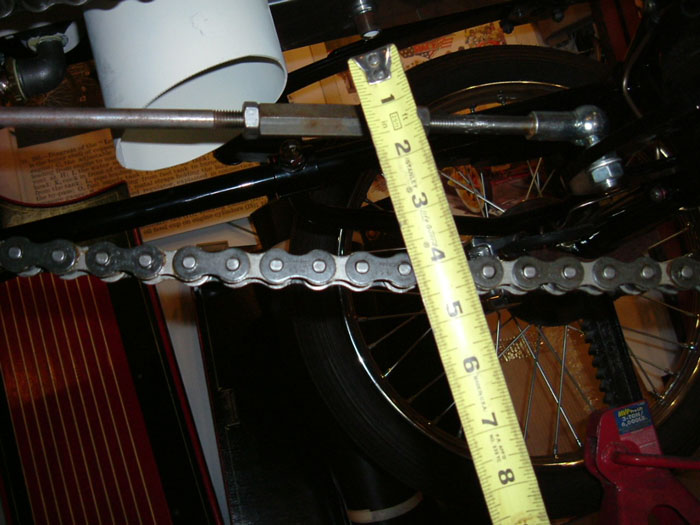
and the ball joint on the rear axle needs to face up. Adjust
the tensioner until you have at least 1 inch of chain deflection
on the lower chain when the upper part of the chain is taught.
The rod length will be about 14.5 inches, ball center to ball
center.
2.0 Hours
April
1
Fuel Tank Feed Modification: This is a modification that will
need to be performed to prevent a whirlpool/ vortex effect at
the fuel inlet when the fuel level is at about 1/3 tank. Brad
Buetlich (California) noticed his burner would go out when the
fuel tank was at about 1/3 or less, and then would relight with
out a problem. Apparently what happens is the burner pump suction
is powerful enough to start a whirlpool/ vortex and will start
to suck in air, which causes low fuel pressure and burner shut
down. I came up with this cheap easy fix. You will need a ¼-18x1.5
inch brass pipe nipple, pipe cap, and a ¼-18 pipe tap.
Remove the fuel tank inlet bushing and tap threads from the
opposite side of the bushing. Thread the pipe nipple into the
bushing tightly. Using a ¼ " bit, drill 4 holes
into the nipple equidistant and close to the end of the bushing.
Install the pipe cap onto the nipple securely, grind off the
hex edges as necessary to fit through the hole in the tank.
Reinstall with sealant as before.
1.0 Hour
I've been informed that the super heater, hand pump, and piping
will be shipped soon.
There will be a burner modification; I just don't have
all the facts yet.
Happy
Building
Rick
Click
pictures to enlarge
Likamobile
Home •
Kits One and Two
•
Kits
Three and Four •
Kits
Four-B and Five
•
Caliper Correction
Kits
Six and Eight •
Kit
Seven •
Kit
Eight •
Kit
Nine •
Kit
Ten •
Kit
Ten Addendum •
Kit Eleven
Kit
Twelve •
Kit
Thirteen •
Kit Fourteen •
Kit Fifteen •
Year End •
Kit Sixteen •
Leaf Spring Modification
Kits
Seventeen / Eighteen •
Engine
Modification •
Boiler
Installation •
Burner
Installation
Fuel
Line, Brake & Throttle Pedal Installation •
Final Kit •
Final Assembly & Steam
Up
Road Test & Modifications
• Purge
Modification